

Overview
The system mainly comprises sensors for valve condition monitoring, data acquisition devices, signal cables, signal transmission equipment, analysis software, and databases.
Based on the characteristics of the various equipment in the project, monitoring points for vibration, runout, pressure, pressure pulsation, and noise are arranged to monitor the valve operating status in real time. The system provides effective online health monitoring of the valves, evaluates their current operating status, issues alarms for abnormal conditions, and performs preliminary fault analysis, enabling maintenance personnel to take timely measures to prevent or reduce major accidents and providing the basis for online adjustment of the equipment. The valve condition monitoring system includes a water hammer pressure monitoring system as its subsystem. The supplier shall have comparable project references with successful applications.
I. Acquisition, Processing and Interaction of Monitoring Data
Through the data acquisition and interaction platform, the system collects operating data, alarm information, and operation records from local automated monitoring equipment in real time, formats them, and writes them into a unified database; control commands issued by application systems are forwarded to the valve condition monitoring system. Specific functions include: receiving data from local monitoring systems, forwarding control commands and data to local monitoring systems, communicating with business applications, and reserving communication interfaces for other local monitoring and control systems.
II. Valve Condition Monitoring and Analysis
(1) Historical Data Analysis and Trend Prediction
The system shall analyze and predict trends of historical operating data such as vibration, runout, pressure, pressure pulsation, and temperature. Historical data shall be displayed and analyzed in multiple dimensions, including bar charts, waveform charts, spectrum charts, waterfall plots, multi-waveform spectrum plots, vibration trend charts, and vibration data lists.
(2) Fault Diagnosis and Analysis
The system shall automatically identify and diagnose valve faults. When an alarm is triggered, the fault diagnosis module is activated: it screens vibration and runout data based on the built-in fault diagnosis knowledge base rules, extracts feature information, and performs rule matching and pattern recognition to determine the most probable fault type, providing results and recommended corrective measures.
(3) Performance Evaluation and Equipment Health Analysis
Using long-term automatically accumulated data under different operating conditions and system test data, together with the provided analysis tools, the system manages current equipment health and historical trends from multiple dimensions—equipment model, fault category, development trend, and historical alarm reports. It can dynamically evaluate the dynamic and steady-state performance of equipment, analyze possible fault causes and risks, and recommend inspection and maintenance strategies.
(4) System Self-Check and Analysis
The system has self-diagnostic capability. Faults in the hardware of the valve monitoring system (such as sensors, data acquisition units, and cables) shall be indicated as alarms in the software, and the affected data shall be excluded to prevent erroneous data from being used in subsequent secondary processing and compromising the credibility of the entire system.
After each system overhaul, the self-diagnostic program shall be run first to verify that the software and hardware of the entire system are functioning normally.
(5) Types and Quantities of Monitored Valve Objects
a) Pump House and Plant-Area Valve Wells: One monitoring cabinet is installed in the pump house. Sensor leads from the monitored valves in the pump house and plant-area valve wells are routed into this cabinet, and data is transmitted via optical fiber to the server in the central control room.
b) Air Valve Wells: One monitoring box (sized per actual use) is installed in each air valve well. Sensor leads are routed into the box, and data is transmitted to the server in the central control room via a signal transmitter. The box is powered by a wind-solar hybrid power supply.
c) Interconnected Valve Wells: One monitoring box (sized per actual use) is installed in each interconnected valve well, with sensor leads routed into the box. Data is transmitted to the server in the central control room via a signal transmitter, powered by a wind-solar hybrid power supply.
d) Surge Towers: One monitoring box (sized per actual use) is installed in each surge tower shaft, with sensor leads routed into the box. Data is transmitted to the server in the central control room via a signal transmitter, powered by a wind-solar hybrid power supply.
e) Flow-Regulating Valve Wells: One monitoring cabinet (size to be determined) is installed in the pump house. Sensor leads from the monitored valves in the flow-regulating valve wells are routed into this cabinet, and data is transmitted to the server in the central control room via a signal transmitter.
III. Multi-Mode Data Acquisition Terminal
The multi-mode data acquisition terminal features multiple fault tolerance, self-diagnostics, and anti-interference capability.
The terminal can acquire and analyze signals from eddy current sensors, velocity sensors, accelerometers, pressure transmitters, noise, voltage, and current, with 24-bit A/D conversion accuracy for each channel. All modules operate independently—a fault in one channel or module does not affect the normal operation of others. The terminal adopts a synchronous acquisition mode, supporting full-channel parallel triggered sampling, real-time acquisition, and selective data storage. After high-speed real-time acquisition, data is checked for abnormal features and stored intelligently to avoid redundancy. The data acquisition and monitoring unit shall therefore be an independent unit equipped with a high-performance processor, capable of independently performing high-speed, large-capacity data acquisition and intelligent storage.
The terminal directly powers each sensor—no separate sensor power supply device is required—and each sensor power channel has short-circuit protection. The terminal is equipped with a dual redundant power supply to improve power reliability.
The acquisition terminal is used for system configuration and monitoring value display. It runs an embedded operating system permanently stored on the built-in memory card of the module; the control module carries a large-capacity storage module for long-term historical data and alarm data, supports post-incident review (event playback), and continues data acquisition and storage during communication failures (up to 3 weeks or more), automatically uploading the stored data to the host server once communication is restored. The data acquisition and monitoring unit supports alarm setpoints configured per operating condition.
IV. Data Server
One high-performance, large-capacity online monitoring data server is installed in the central control room for communication, computing, and storage management of real-time and historical condition monitoring data of all valves on the pipeline. Within the pump house and plant area, communication uses optical fiber via optoelectronic transceivers; other communication uses 4G signal transmission modules, supporting valve operating status analysis and diagnosis.
V. Product Information
Acceleration Vibration Sensor: Model 310A-80
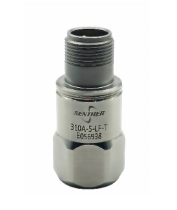
Product Features: Rugged design, corrosion-resistant, sealed, isolated housing, EMI/RFI shielding, shock-resistant.
High-Speed Data Acquisition Instrument: WSS-25931u16
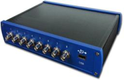
Product Features:
- USB interface with hot-plug support (Plug and Play);
- External computer device, convenient and portable;
- 16-channel synchronous acquisition;
- Compact size, low power consumption, high precision, easy configuration;
- As a compact USB device, it offers unique advantages: easy connection, no external power required, plug-and-play, and hot-swapping while powered on;
- Widely used in scientific research and industrial measurement and control.
