

I. Solution Overview
In road-related tests such as automotive road testing, road roughness assessment, vehicle ride comfort evaluation, and road and bridge structural verification, it is necessary to acquire static acceleration, low-frequency vibration, and high-frequency shock signals along the X/Y/Z axes during vehicle travel, so as to complete road profile collection, bump evaluation, and load data analysis. Conventional piezoelectric vibration sensors cannot measure static gravitational acceleration and suffer from zero drift, making it difficult to fully capture signals arising from low-speed and static tilt conditions.
This solution adopts the 839 Series triaxial static-response MEMS accelerometer, which can simultaneously acquire triaxial acceleration signals, covering static response, low-frequency vibration, and high-frequency shock. It is suitable for various complex operating conditions, including vehicle proving grounds, public roads, and bridge decks. The sensor outputs analog voltage signals and can be directly connected to general-purpose data acquisition equipment to perform road–vehicle coupled vibration testing and output raw test data for road evaluation, vehicle ride comfort, and load spectrum analysis.
II. Test Application Scenarios and Test Objectives
Main Test Scenarios
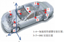
Automotive Road Load Data Acquisition (RLDA): Acquire vibration acceleration at the vehicle body, chassis, and seat positions to obtain road load spectra, providing raw input data for bench simulation.
Vehicle Ride Comfort Testing: Measure triaxial vibration at the seat, footrest, and steering wheel positions to evaluate the bumpiness experienced under different road surfaces.
Road and Bridge Pavement Verification: Conduct tests on bridge approach jumping, pavement potholes, and bridge driving vibration response to assess pavement defect severity.
Severe Road Surface Testing: Measure shock acceleration on harsh road conditions such as speed bumps, bumpy roads, and Belgian block pavements.
Test Objectives
Acquire complete time-domain acceleration signals along the X (longitudinal), Y (lateral), and Z (vertical) axes during vehicle travel;
Simultaneously measure static gravity components and dynamic vibration/shock, covering both low-frequency static and high-frequency shock conditions;
Output stable and reliable raw data for PSD analysis, road roughness conversion, and ride comfort index calculation.
III. Core Sensor Product Recommendation: 839 Triaxial Static-Response Accelerometer
The 839 Series is a capacitive MEMS triaxial accelerometer that supports static response and simultaneously outputs triaxial analog voltages, making it highly suitable for on-road vehicle testing scenarios.
Core Product Advantages (Road Testing Fit)
Static response supported: Unlike piezoelectric sensors, it can measure static gravity; the zero point does not drift when the vehicle pitches or tilts, ensuring data integrity in low-speed road testing.
Wide measurement range of 2–500 g: For routine road comfort testing, ±2 g or ±10 g is selected; for severe shock road surfaces, ±50 g or ±100 g is used to meet different road conditions.
Wide frequency response: From DC static up to 7,000 Hz, covering both low-frequency road bumps and high-frequency wheel/chassis shock.
Excellent temperature stability: Built-in temperature compensation, operating over a wide temperature range of −40°C to +125°C; sensitivity temperature drift is controlled within ±2% under outdoor day–night temperature variations, ensuring reliable outdoor road test data.
High shock resistance of 5,000 g: The sensor will not be damaged under large shock conditions such as potholes and speed bumps.
Electrically isolated output: The signal ground is insulated from the measured object, reducing ground-loop noise interference in vehicle environments; the output is a standard analog voltage of 2.5 V ± 2 V, which can be directly connected to ordinary voltage-input data acquisition instruments.
Flexible installation: Supports M3 screw fastening or adhesive mounting; the housing weighs only 17 g, imposing minimal additional mass on the measured structure.
Selection Guide (Road Testing Reference)
Passenger car comfort and ordinary highway road profiles: 839-10 (±10 g) or 839-20 (±20 g)
Proving grounds and bumpy/shock road surfaces: 839-50 (±50 g) / 839-100 (±100 g)
Cable length: select 1 m or 3 m according to the vehicle test layout.
IV. Complete Test System Composition
The complete system consists of 839 triaxial accelerometers, data acquisition equipment, a host analysis computer, and associated accessories:
Sensing unit: 839 triaxial accelerometers (multiple units can be deployed synchronously), with optional LEMO connector PJ0048; mounting accessories PM0346 M3 hex socket screws and PM0073 washers.
Data acquisition unit: IN-3062 8-channel data acquisition system is recommended; general-purpose analog voltage acquisition modules may also be used, provided they support multi-channel synchronous sampling.
Power supply unit: 8–36 V DC regulated power supply; the vehicle's 12 V/24 V power supply can be used directly.
Host computer: Performs parameter configuration, data storage, and time-domain/frequency-domain post-processing analysis (PSD power spectrum, filtering, road index conversion).
Auxiliary: GPS module (records vehicle speed and position, correlates with road surface points), cable ties, and high-temperature tape for cable fixation.
System connection logic: DC power supplies the 839 sensor → X/Y/Z triaxial analog voltage signals are connected to the analog input channels of the acquisition device → the acquisition device transmits data to the host computer for storage and analysis.
VI. Test Implementation Procedure
Preparation: Confirm that the sensor model and range match the test conditions; check cables, power supply, and acquisition equipment. The sensor requires less than 100 ms of power-on warm-up to reach a stable state.
Static calibration and zeroing: Park the vehicle horizontally and stationary, record the sensor zero output of 2.5 V, and complete static zero calibration.
Installation and fixation: Align the sensor with the vehicle coordinate system, secure the body, and fix the cable with cable ties at intervals to eliminate spurious vibration signals caused by cable movement.
Condition testing: Conduct driving tests on different road surfaces and at different vehicle speeds according to the test plan; simultaneously record GPS vehicle speed and position information. Recommended sampling frequency: 1–2 kHz for routine comfort testing; 5–10 kHz for severe shock road surfaces.
Data acquisition and storage: Synchronously record the raw voltage signals of X/Y/Z triaxial acceleration.
Post-processing analysis:
Convert voltage signals to acceleration in g (based on sensor sensitivity in mV/g);
Filter out high-frequency noise; perform PSD power spectral density analysis;
Calculate vibration RMS values and ride comfort evaluation indices, and use position information to locate pavement potholes and bridge approach jumping defects.
V. Solution Precautions
Range selection: An excessively small range will cause signal clipping and saturation; an excessively large range will reduce the signal-to-noise ratio. For routine road testing, ±10 g to ±50 g is preferred.
Vehicle power supply: It is recommended to add simple filtering to the vehicle power supply to reduce generator ripple interference; utilize the signal-to-housing insulation characteristic of the sensor to reduce common-mode noise.
Temperature effects: Although the 839 has built-in temperature compensation, for long-duration outdoor high/low-temperature testing, sensitivity temperature correction is recommended during data processing.
Avoid cable stress: Road bumps will pull on cables; fix the cable at a position 10 cm from the sensor body to prevent stress from being transmitted into the sensor body and generating spurious signals.
VI. Summary of Solution Advantages
1. The 839 MEMS triaxial static accelerometer can measure both static and dynamic vibration, compensating for the shortcomings of piezoelectric sensors, which cannot measure static signals and lose low-frequency signals; it is highly suitable for on-road vehicle testing.
2. A single sensor simultaneously outputs X/Y/Z three axes, reducing the number of measurement points and simplifying system setup; the standard analog voltage output is compatible with most acquisition devices on the market.
3. Wide temperature range, high shock resistance, and sealed housing adapt to harsh field road environments, ensuring stable performance in long-term testing.
4. Complete accessories and calibration reports are provided, enabling out-of-the-box use in R&D testing and third-party verification projects.
5. Ordering example: 839-20-3 represents a range of ±20 g, cable length of 3 m, supplied with M3 mounting screws and washers.
